Hardware-Based Keylogger
Hardware-Based Keylogger.
- Installed between the USB port and the keyboard, captures all keystrokes.
- Hardware-based, invisible to antivirus.
- Two hardware specifications for various implantation scenarios.
- Wi-Fi features for remote access.
- Built-in 3MB flash storage with automatic circular.
- Auto upload captured keylogs with AES-128 encryption via ntfy.sh or custom HTTP.
- Supports automatic scanning of nearby open Wi-Fi networks for internet access.
- Multilingual interface (English / 中文 / Русский).
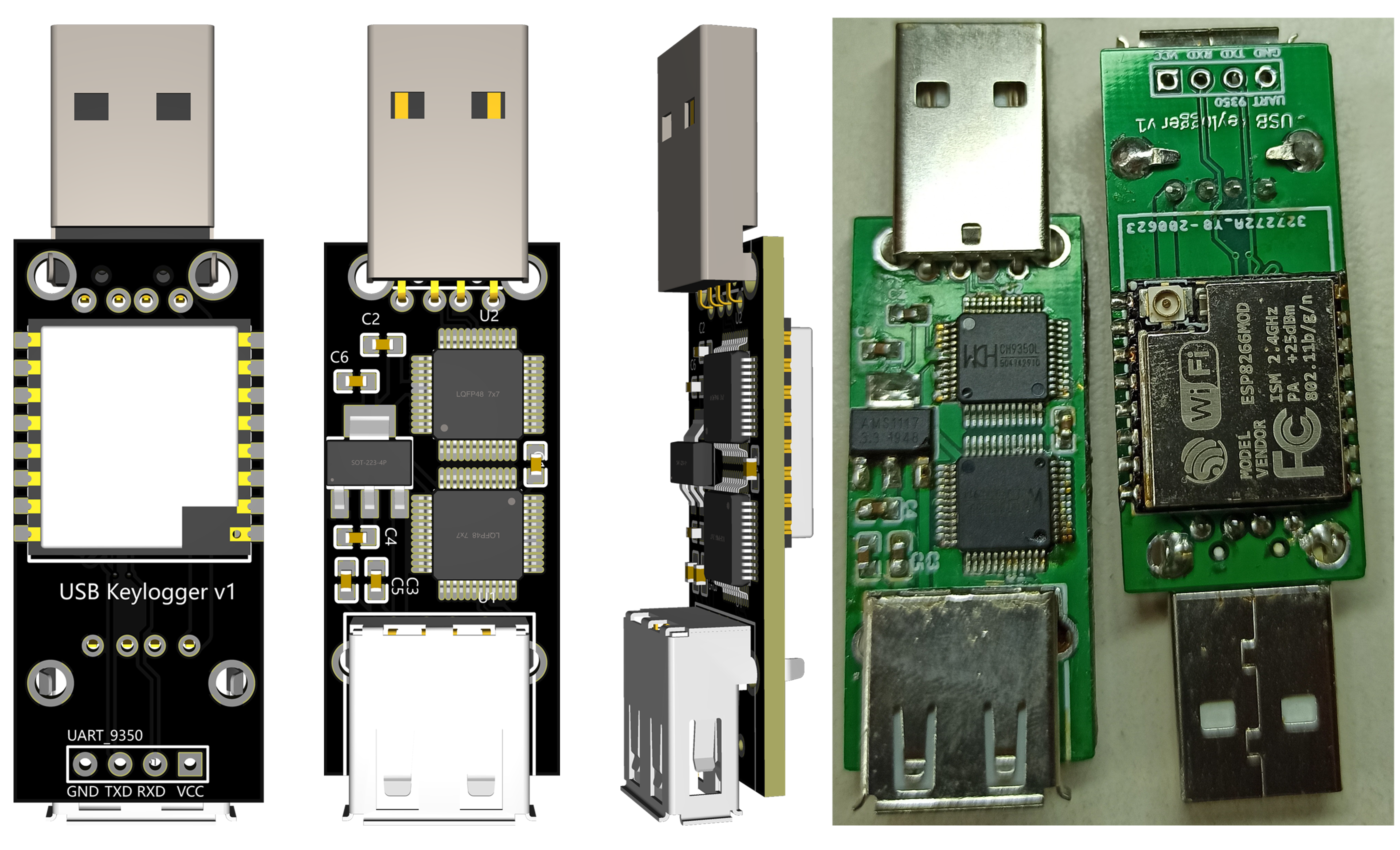
USBKeylogger is available in two hardware specifications:
-
Compact Model: Smaller in size, can be installed inside the keyboard (Example here).
-
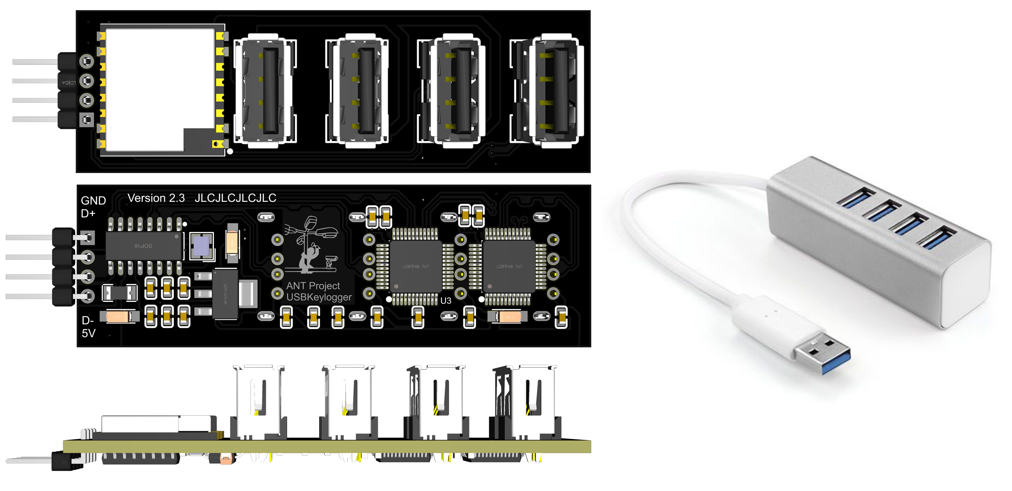
USB Hub Model: Built into a USB Hub (only the bottom port has keyboard logging functionality).
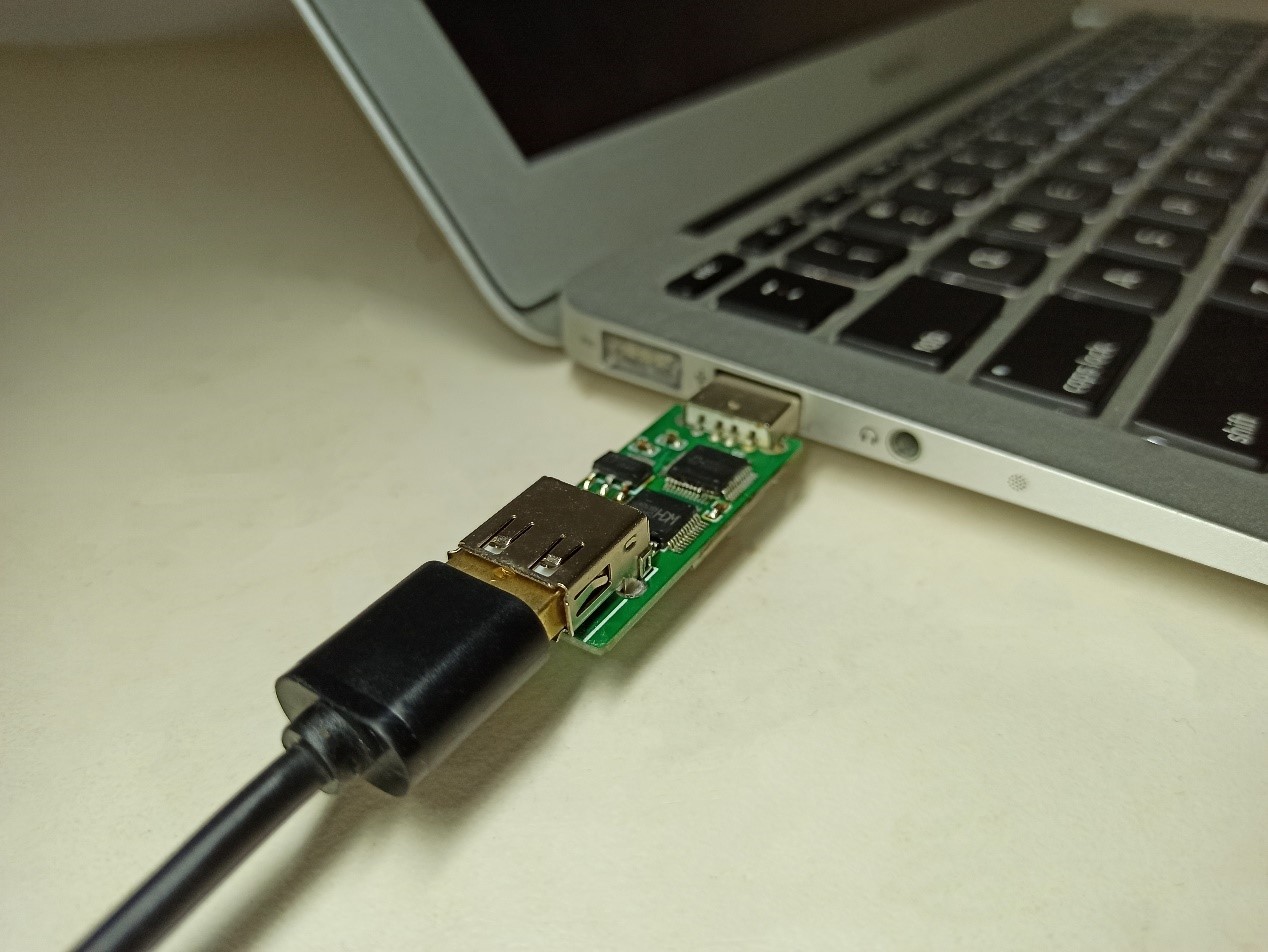
Plug the USB Keyboard into the female USB port of the USBKeylogger, then plug the USBKeylogger into the computer.
Connect to the Wi-Fi hotspot of USBKeylogger, navigate to http://192.168.5.1/.
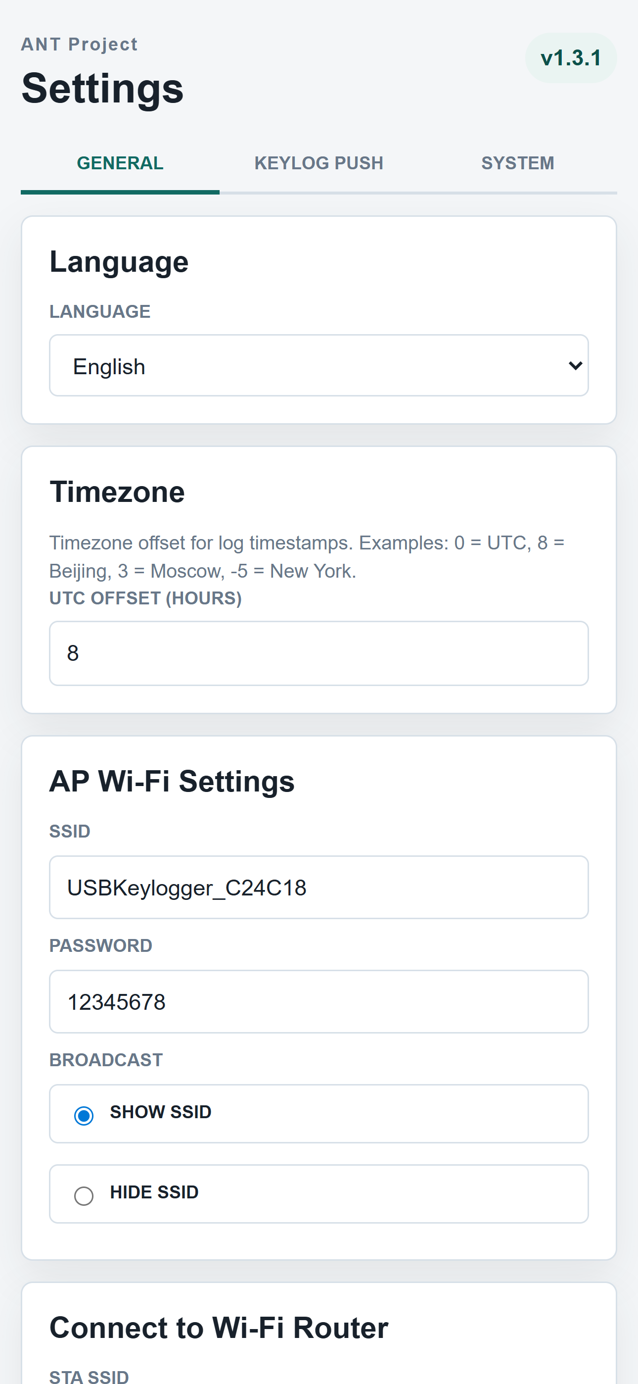
- Default SSID:
USBKeylogger_XXXXXX(last 6 digits of MAC address), default password:12345678 - After logging in, it is strongly recommended to change both the hotspot password and the web interface password.
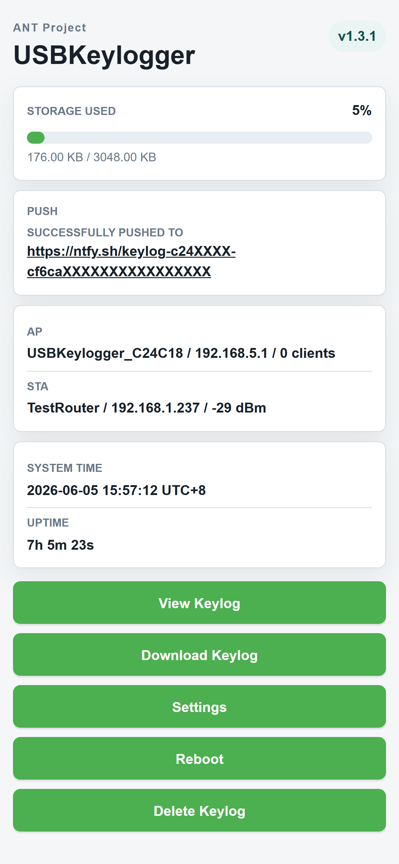
Click "View Keylog" on the home page to view online, or "Download Keylog" to save as a text file.
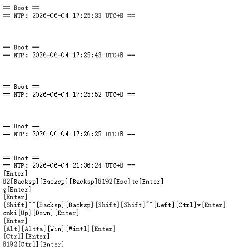
Each boot is marked in the keylog. If internet is available, the boot time is also recorded via NTP.
Once USBKeylogger is connected to a Wi-Fi network with internet access, it can automatically push keylogs to a designated server. All push data is AES-128 encrypted — the server only receives ciphertext. Download the ciphertext and decrypt it locally with the decryption tool.
Go to Settings → General, fill in your router's SSID and password under "Connect to Wi-Fi Router", save and reboot. The device will maintain both the AP hotspot and the STA connection simultaneously.
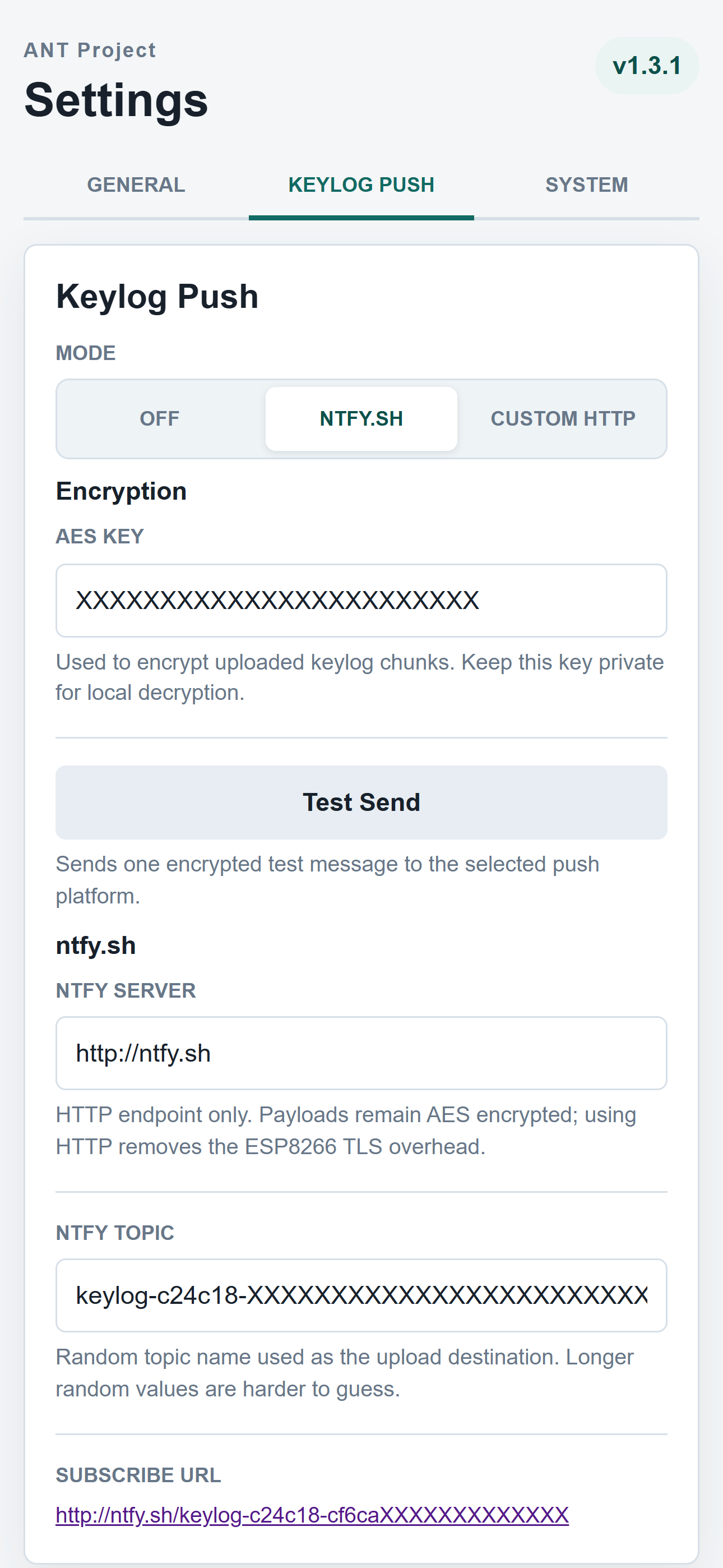
Go to Settings → Keylog Push and select a push mode. ntfy.sh is recommended.
ntfy.sh is an open-source push notification service that requires no account registration.
-
In "ntfy Server", enter the server address. The default is
http://ntfy.sh(free public server). -
A random string is generated in "ntfy Topic" as the channel name (can be changed manually).
-
A 32-character AES encryption key is generated in "AES Key". Save this key carefully.
-
Click the generated subscription link to view push history. Also save this push link.
-
Click "Test Send" to verify the push channel is working.
Note: The public ntfy.sh server retains push messages for only 3 hours. It is recommended to self-host an ntfy server and update the server address accordingly.
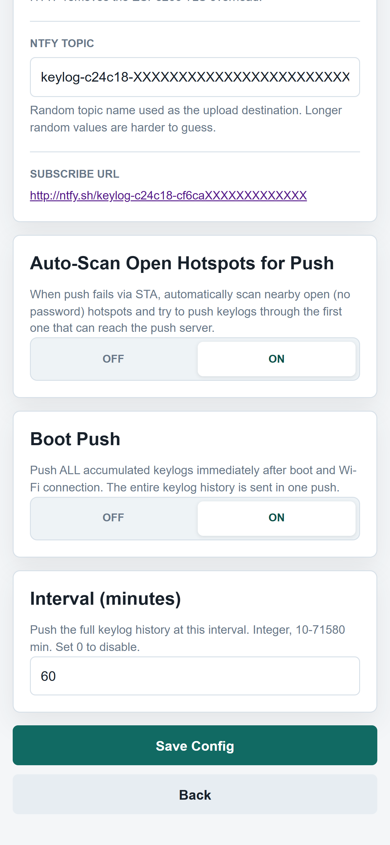
The push schedule controls when keylogs are sent. Boot push and scheduled push are independent and can both be enabled at the same time:
- Boot Push: After each boot and Wi-Fi connection, the full keylog history is pushed immediately. Enabled by default.
- Scheduled Push: While the device is running, the full keylog history is pushed at the configured interval (10–71,580 minutes). Suitable for devices that run for extended periods without rebooting.
Visit the generated ntfy.sh subscription link and download the attachment. The content is encrypted ciphertext in the format AES128CBC:<Base64>.
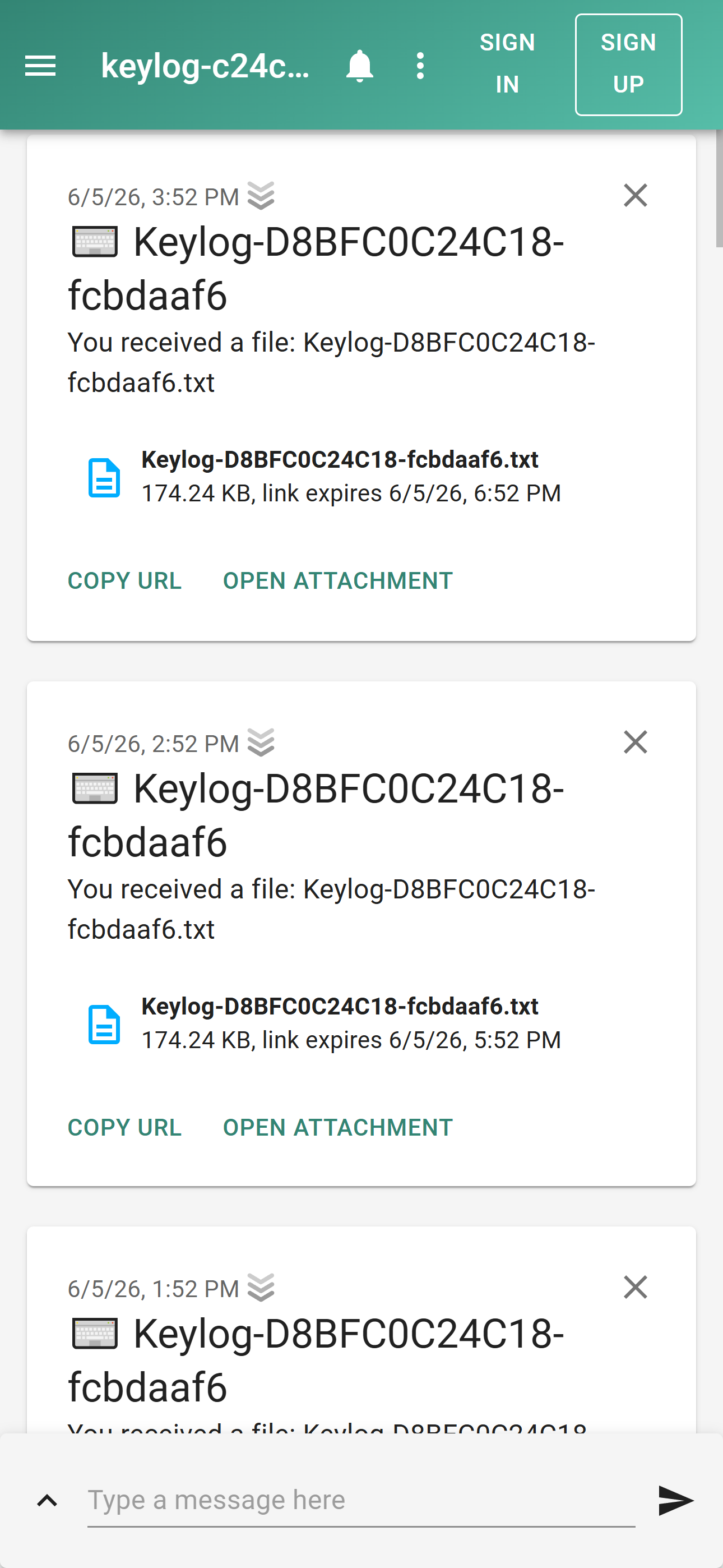
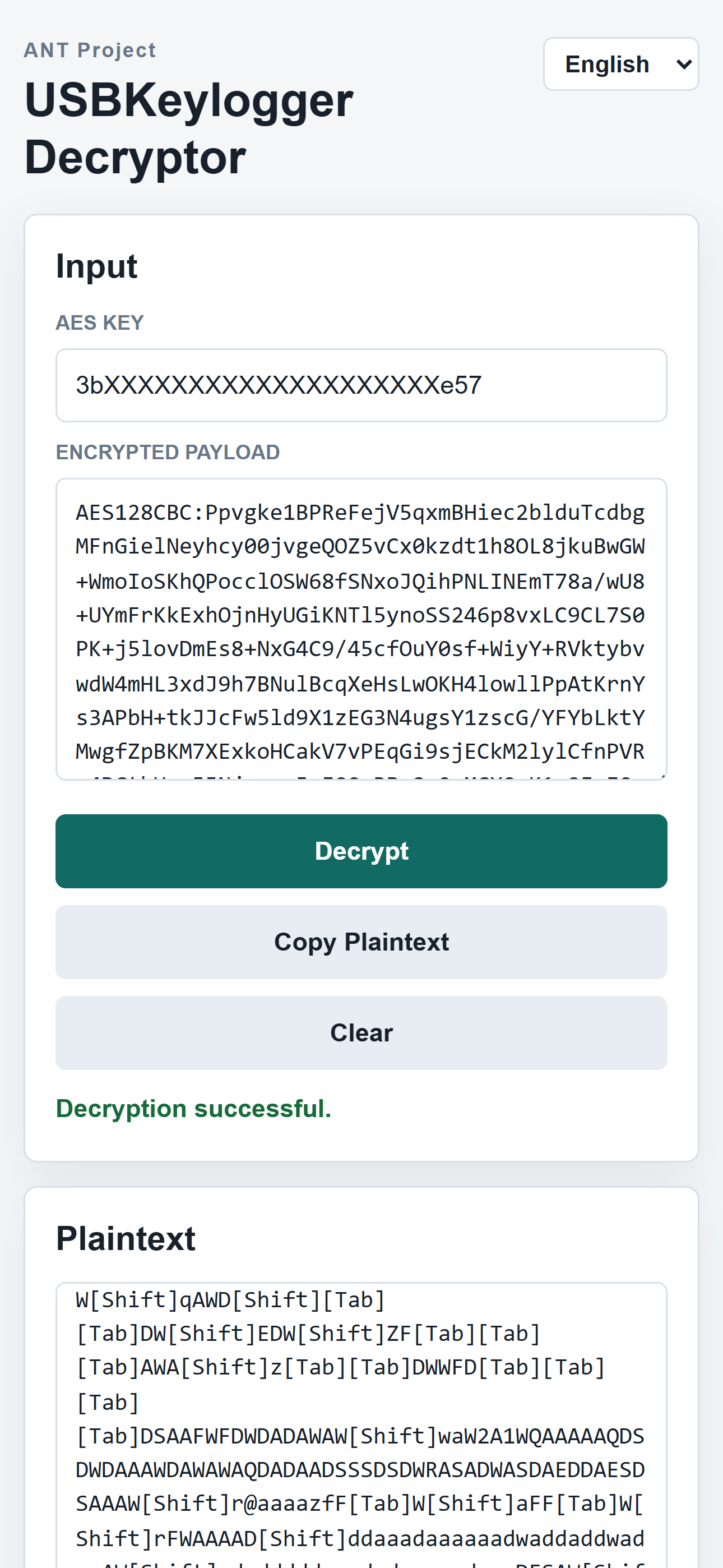
Use the included KeylogDecrpyt.html to decrypt it locally in your browser.
- Open
KeylogDecrpyt.htmlin a browser - Paste the AES key from the settings page into the "AES Key" field
- Paste the encrypted content into the "Encrypted Payload" field
- Click "Decrypt" — the plaintext keylog will appear below
When push is configured but the STA network is unavailable (or no STA is configured), this feature can serve as a fallback push channel.
How it works:
- The device detects that STA push has failed
- It automatically scans all nearby open (no password) Wi-Fi hotspots
- It connects to each one in turn, attempting to reach the push server
- After a successful push, the successful hotspot is saved and tried first on the next attempt
Warning: A specific batch of CH9350L chips contains a bug. When a button is pressed for 2 seconds, the CH9350 continuously sends the key value to the HOST for over 2 seconds, or even indefinitely, until another button is pressed to interrupt it. This is an inherent bug in the CH9350 chip itself, Please replace the chip batch.
The hardware design of USBKeylogger is open-sourced on OSHWHUB:
- Compact Model: https://oshwhub.com/ant-project/USBKeylogger
- USB Hub Model: https://oshwhub.com/pusheax/usbkeylogger_v2_bak2
| Component ID | Description | Package Type | Quantity |
|---|---|---|---|
| C7,C8 | 1uF Capacitor | C0603 | 2 |
| C9,C10,C11,C12 | 100nF Capacitor | C0603 | 4 |
| MK2 | ESP-07S | WIRELM-SMD_ESP-07S | 1 |
| U4 | AMS1117-3.3 | SOT-223-4 | 1 |
| U5,U6 | CH9350L | LQFP-48 | 2 |
| USB3 | To Keyboard | USB-A-TH_USB-A-F-90 | 1 |
| USB4 | To Host | USB-A-TH_AM90 | 1 |
| Component ID | Description | Package Type | Quantity |
|---|---|---|---|
| C1,C3,C5,C9,C10,C11,C13,C15 | 10uF Capacitors | C0603 | 8 |
| C2,C4,C6,C8,C12,C14,C16,C18,C20 | 100nF Capacitors | C0603 | 9 |
| C7,C17,C19 | 10uF Tantalum Capacitors | CAP-SMD_L3.2-W1.6 | 3 |
| F1 | ASMD1206-200 Fuse | F1206 | 1 |
| MK1 | ESP-07S | WIRELM-SMD_ESP-07S | 1 |
| U1 | SL2.1A | SOP-16 | 11 |
| U2 | AMS1117-3.3 | SOT-223-4 | 1 |
| U3,U4 | CH9350L | LQFP-48 | 2 |
| USB1,USB2,USB3,USB4 | 916-351A1024Y10200 | USB-A-TH_USB-M-8 | 4 |
| X1 | 12MHz | CRYSTAL-SMD | 1 |
| N/A | USB Hub Case | N/A | 1 |
Here are a brief steps to make your own USBKeylogger:
- Download the Gerber files for the Compact Model or the USB Hub Model of USBKeylogger and send them to a PCB manufacturer for production. There are no special manufacturing requirements for the Compact Model, but for the USB Hub Model, the board thickness of 1.2mm is recommended.
- Download the firmware for the ESP-07S module here. Open it with Arduino and flash it onto the ESP-07S module using a programmer.
- Refer to the BOM section and solder the components. When installing the Compact Version inside the keyboard, the USB connector can be omitted and instead soldered directly to the internal USB wires of the keyboard.
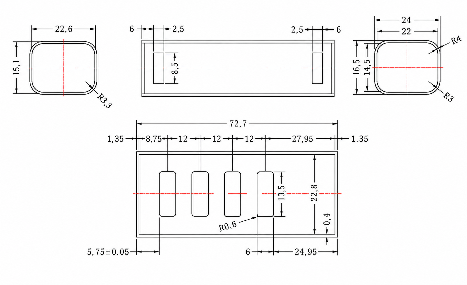
- For the USB Hub Model, you also need to purchase a case, the specifications of which should meet the following requirements:
The firmware targets the ESP-07S / ESP8266 module. In Arduino IDE, install the esp8266 board package and select Generic ESP8266 Module.
Required libraries:
- ESPAsyncTCP
- ESPAsyncWebServer
- ESPAsyncDNSServer
Recommended board menu settings:
| Menu item | Setting |
|---|---|
| Board | Generic ESP8266 Module |
| Upload Speed | 115200 |
| CPU Frequency | 80 MHz |
| Crystal Frequency | 26 MHz |
| Flash Size | 4MB (FS:3MB OTA:~512KB) |
| Flash Mode | DOUT (compatible) |
| Flash Frequency | 40MHz |
| Reset Method | no dtr (aka ck) |
| Debug port | Disabled |
| Debug Level | None |
| lwIP Variant | v2 Lower Memory |
| VTables | Flash |
| C++ Exceptions | Disabled |
| Stack Protection | Disabled |
| Erase Flash | Only Sketch; use All Flash for a clean reinstall |
| Espressif FW | nonos-sdk 2.2.1+100 (190703) |
| SSL Support | Basic SSL ciphers (lower ROM use) |
| MMU | 32KB cache + 32KB IRAM (balanced) |
| Non-32-Bit Access | Use pgm_read macros for IRAM/PROGMEM |
| Builtin Led | 2 |
The frontend code is located in USBKeylogger.ino/common_fixed.js, which contains CSS styles, i18n dictionaries, and page logic.
After modifying the frontend, run the build tool to compress and embed the JS:
cd USBKeylogger.ino
python rebuild_html_h.py
This script gzip-compresses common_fixed.js and writes the resulting C array into the JS_Common_GZ section of USBKeylogger/html.h.